The Sig P250 model is one of the more popular models in the Sig P Series. Early versions of this pistol, such as the P220, eventually led to the development of the P250. However, in early 2018 this model was discontinued by Sig Sauer, despite its success. If you’ve landed on this page, you’re probably wondering how to disassemble a Sig Sauer P250.
In order to field strip this weapon, the steps are extremely easy, and straight forward. However, the biggest problem many owners have is cleaning the trigger assembly. Here are the 7 steps to field strip a Sig Sauer P250. Afterwards, we’ll discuss how to take apart the fire control unit. At the end of the article we’ll discuss how to put it all back together.
Table of Contents
Steps to Field Strip A Sig Sauer P250
- Drop the magazine
- Lock the slide and inspect to ensure the weapon is clear
- Rotate the takedown lever so it is perpendicular to the floor, it should not be able to turn further
- Holding the slide, slowly return to forward position
- Slide is removed by continuing forward along rail on frame
- Turn the slide over, and remove recoil spring/recoil spring guide
- Remove the barrel by moving it forward slightly and lifting up then moving to rear of slide
Congratulations, you’ve field stripped your Sig Sauer P250. However, if you’re attempting to remove the trigger assembly (also known as the fire control unit – FCU), additional steps are required. Furthermore, you’ll need a fine point tool (e.g. a thin shank/shaft screwdriver) or you can get this gunsmithing tool from Amazon to assist with removing pins.
Steps to Remove the Trigger Assembly (Fire Control Unit – FCU)
- Once the P250 is field stripped, push the takedown lever out of the frame, toward the lever side.
- Gently lift the front of the FCU using the two rails, partially removing the unit
- Afterwards you’ll need to pull back on the hammer to allow removal of the FCU from frame
- Next, remove the trigger bar spring by lifting gently on the coil to allow hooked end to free from trigger bar
- Afterwards, pull the trigger all the way forward to free up the trigger bar and allow both to separate from the rest of the unit
- Next remove the slide catch lever pin by pushing it out; CAUTION: parts under tension
- Remove slide catch lever and slide catch lever spring from remainder of FCU
- Remove the hammer pivot pin
- Next partially remove the hammer strut pin; CAUTION: parts under tension
- This will allow you to remove both the large and small mainspring
- At this point the safety lever should fall freely
- Removing the hammer strut pin completely will allow the hammer to separate from the FCU
Reassembling the pistol requires that you do the reverse process. However, there are some subtleties that we’ll cover in this article both when disassembling and re-assembling the FCU and pistol. Let’s take a closer look.
Setting Up Your Workstation
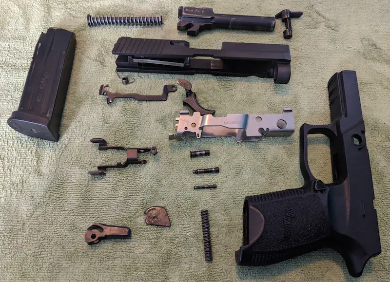
A tidy workstation is important when preparing to field strip your weapon. Because there are many small pieces to keep track of, clear a workspace before beginning. Whenever you begin the process of field stripping a weapon, lay out a lint free towel or other lint free cloth — I use a micro fiber towel. If you have an oversized mouse pad, this can also be used. You can also pick up this TekMat pad on Amazon with clear reference to the parts mentioned in this tutorial. Ensure that all of the parts will fit on your workstation with ease. For the purposes of field stripping the Sig P250 and breaking down the trigger assembly, a 11″ X 7″ workstation should be sufficient.
Clearing the Weapon
The first set of steps are dedicated to clearing the weapon. Begin by dropping the magazine. Because you drop the magazine first, an unintentional discharge will not result in another round being chambered. To drop the magazine, compress the magazine catch (see fig. 1). The magazine should slide out freely, and drop into your hand. However, some magazines will only eject slightly, and will need you to assist with removing the magazine completely.
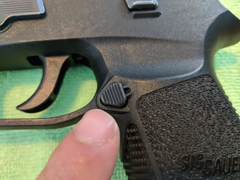
fig. 1 – magazine catch button
The Sig P250 doesn’t have any external safeties you need to disable. Therefore, the next step in the process is to lock the slide in the rearward position using the slide catch lever (see fig. 2). Next inspect the chamber to ensure there is no cartridge. You should be able to see clearly to the floor (or table).
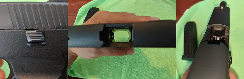
fig. 2 – from left to right; slide catch lever, top view of cleared Sig P250, empty chamber of Sig P250
Removing the Slide Assembly
Now that the weapon is clear, you can begin field stripping the weapon. Next, with the slide locked in the rearward position, rotate the takedown lever slightly more than 90 degrees so it is perpendicular to the floor. The takedown lever should not be able to rotate further. See fig. 3 to see the takedown lever in the correct position.
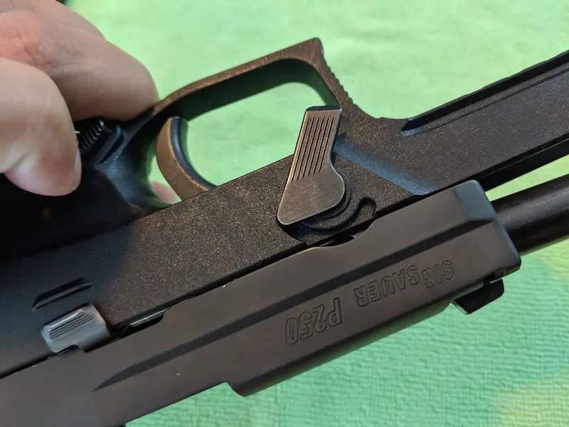
fig. 3 – takedown lever in down position
At this point, grip the slide firmly, and pull back gently. This will disengage the slide stop lever and allow the slide to travel forward. Keep your grip on the slide and guide it off of the frame. Ensure you hold the slide since it is under tension from the recoil spring.
Barrel, Recoil Spring, and Recoil Spring Guide
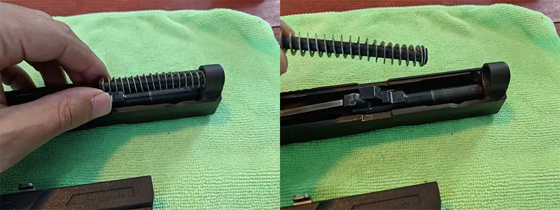
fig. 4 – lift up on rear of recoil spring guide to remove
Next, flip the slide assembly over. Afterwards, lift up on the recoil spring and recoil spring guide on the end closest to the rear of the slide to remove them (See fig. 4). These pieces will come out together, and are essentially one piece in terms of field stripping your weapon. Set these pieces aside on your workstation.
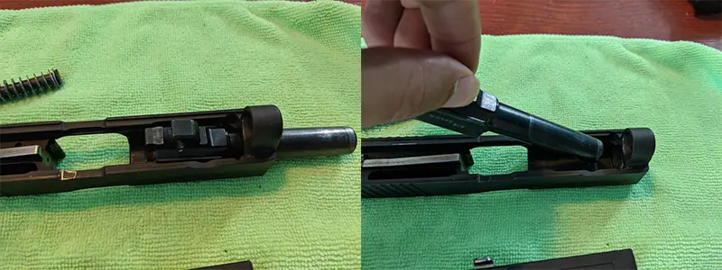
fig. 5 – move barrel forward (exaggerated) then lift and move toward rear of slide to remove
Once the spring and spring guide are removed, you will have access to the barrel. Move the barrel forward slightly, then lift up and pull toward the rear of the slide to remove the barrel (See fig. 5). Congratulations, you’ve successfully field stripped your Sig Sauer P250!
Separating the Fire Control Unit (Trigger Assembly)
By far, disassembling the trigger assembly is more difficult than field stripping the P250. However, with a patience and by paying close attention to this tutorial, you should have it out in no time. It’s important to remember that many of the parts of the fire control unit are small and can easily be lost. Furthermore, some pieces are under tension. Therefore, take extra care when disassembling or reassembling the trigger assembly.
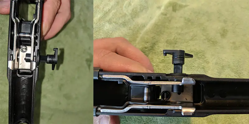
fig. 6 – slide the takedown pin out toward the side with the lever
The first step in disassembling the trigger assembly is to separate it from the grip module. In order to accomplish this, remove the takedown lever by pushing on the pin toward the lever side (See fig. 6). You may need to work this a little bit to actually free from the holes allocated on the grip module and fire control unit. Remove this completely and set aside before proceeding.
Extracting the Fire Control Unit From Grip Module
I’ll start by saying many of the following steps are more of an art than a science. I am providing tips and tricks that have helped me. However you may discover a way that works better for you. Regardless, you’ll need to do this several times to discover what process works best for you. Alright then, moving on.
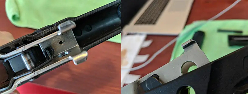
fig. 7 – lift gently on tabs since you’ll need to maneuver trigger to fully extract the FCU
Once you’ve removed the takedown lever completely, lift up on the frame of the fire control unit toward the front of the grip module. There will be two (2) small metal protrusions on either side which will allow you to lift the unit (See fig. 7). Do not simply yank on the frame to try and free if from the grip module.
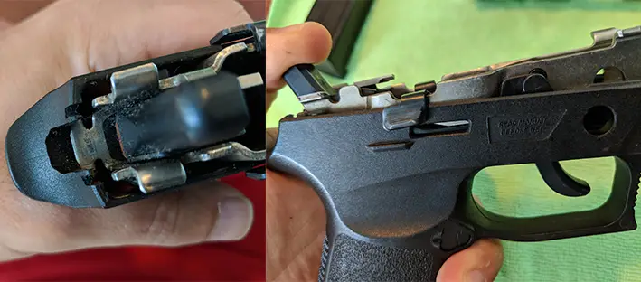
fig. 8 – the image on the left shows the tab already partially dislodged. Pulling back on the hammer can help, or you can move the entire unit forward.
Next, your goal is to dislodge the metal tab (See fig. 8) at the rear of the FCU which will allow it to free the unit from the grip module. You’ll notice that you have to allow space for the trigger to slide through the grip module to accomplish this. To assist with removing the unit, pull back gently on the hammer with your thumb OR move the entire trigger assembly forward to allow the trigger to clear the opening.
Taking Apart the Trigger Assembly
After separating the fire control unit from the grip module, you’re ready to break down the fire control unit for cleaning. First, you need to remove the trigger bar spring, a closeup is provided below (See fig. 9). I’ve found the best way to do this is by lifting the spring upward at the coil. This will release the hooked end, and the bent end should slide out easily.
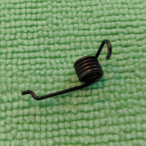
fig. 9 – Trigger bar spring detail
Trigger and Trigger Bar Removal
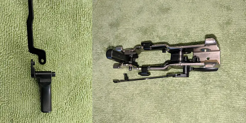
fig. 10 – On the left the trigger bar attaches to the trigger using the hole and pin on trigger. On the right is the partially removed trigger and trigger bar spring.
Afterwards, remove the trigger bar by putting the trigger into the forward most position. This will allow the trigger bar to free itself from the pin that holds it in place. From there, simply slide the trigger out laterally, which will free up the trigger bar and it will separate completely from the rest of the unit. It is worth noting for re-assembly that the trigger bar attaches using a pin on the trigger which fits through the eye of the hole on the trigger bar (See fig. 10).
Slide Catch Lever, Spring, and Pin
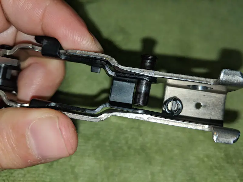
fig. 11 – removing the slide catch lever pin allows entire slide catch assembly to be removed. Use caution as this is under slight tension and the spring/washer may fall upon removal.
Afterwards, you will take apart the slide catch lever. It’s advisable to use caution during this step as the slide catch lever spring may be under tension. However, in order to accomplish this, you’ll need to extract the slide catch lever pin (See fig. 11). This is where your gunsmith tool or fine tip screwdriver is will help to extract the slide catch lever pin.
You’ll push the dimpled end of the pin, and the opposite end will have a knob that will assist in removal. Keep the top covered to ensure any tension in the spring does not cause you to lose it. Once the pin is removed, you can extract the slide lever catch from the top of the fire control unit along with the spring.
On my model, the spring fell off easily and after several runs through disassembly I found it easiest to flip the unit upside down for this portion. Also, on my unit there is a small washer that fits atop the spring and around a small knob on the bottom of the slide lever catch.
Taking Apart The Hammer
Probably the most difficult part of disassembling the fire control unit is taking apart the hammer. There are many spring loaded pieces and it is essential that you use extreme caution during the following steps. I will also mention that I do not frequently take this section apart because it is the most difficult section to re-assemble. While a thorough cleaning does require this section be removed, I refrain from doing this unless there is noticeable buildup.
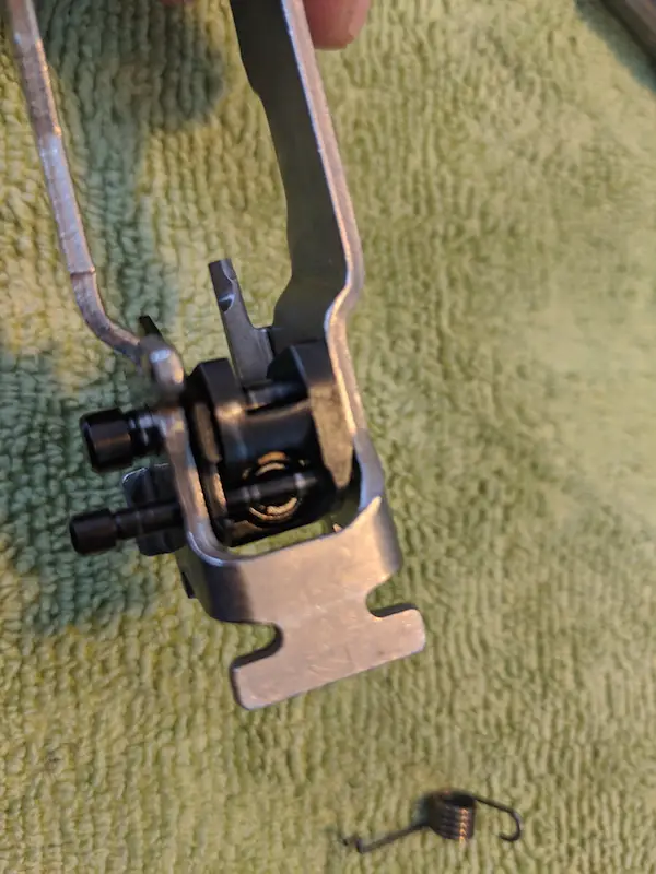
fig. 12 – The larger of the 2 pins is the hammer pivot pin and should be removed first. The smaller of the 2 pins is the strut pin and is under extreme tension and difficult to remove.
Begin the process by extracting the hammer pivot pin (See fig. 12). Press the protruding side in toward the assembly. This will cause a knob similar to slide catch lever pin to pop out on the other side. Next, you’ll need to remove the hammer strut pin, which is the smaller of the two pins. The hammer strut pin is under extreme tension and some amount of force may be required to dislodge it. Press from the same side that you pushed out the hammer pivot pin from.

fig. 13 – mainsprings partially ejected after removing strut pin
Remove the hammer strut pin partially. There are 2 springs that are held in place that are under tension (See fig. 13). Keep your finger covering the bottom of the assembly to prevent loss of the pieces. Next, remove the large and small mainsprings from the bottom of the trigger assembly housing. The smaller fits inside the larger spring. You may notice that the safety lever also falls free at this point (See fig. 14).
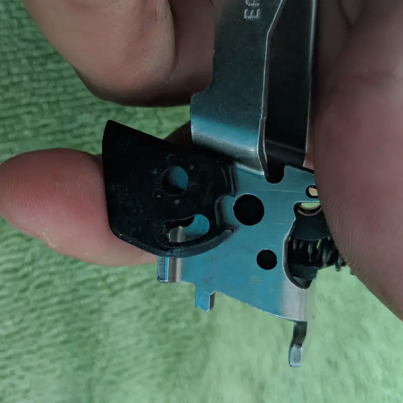
fig. 14 – Safety lever removed from inside housing.
Finally, remove the hammer strut pin completely to allow the hammer to fall completely free. Congratulations, you’ve now disassembled the fire control unit and broken the trigger assembly into all it’s components. Now, get to cleaning because next we have to put the whole thing back together!
Reassembling the Trigger Assembly
If you’ve managed to get everything apart, you’ll notice how difficult it is to get the hammer strut pin out because of the tension from the mainsprings. Guess what? Getting the hammer strut pin back in is even more difficult. This is the single most difficult part to accomplish, and it’s recommended that you have a gunsmith tool to assist.
However, in order to test out the usefulness of my Leatherman OHT, I completed the reassembly using the small flat head attachment. You can see more details about this tool on my EDC tools section.
Unfortunately, it is difficult to take pictures of each step in the process, but I’ll provide some useful images to help with reassembly. Most notably, the location and direction of the applicable pins, as well as how to properly fit the safety lever.
Pin and Lever Positioning
Use the images below (fig. 15 – 16) to ensure the direction of the pins is correct in relation to the trigger assembly housing. They will also provide some indication of how the safety lever should be positioned.
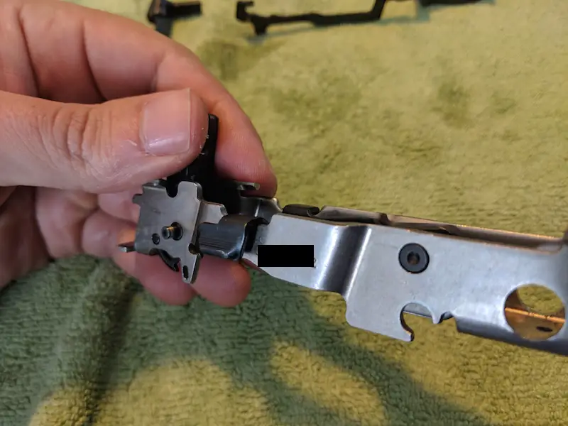
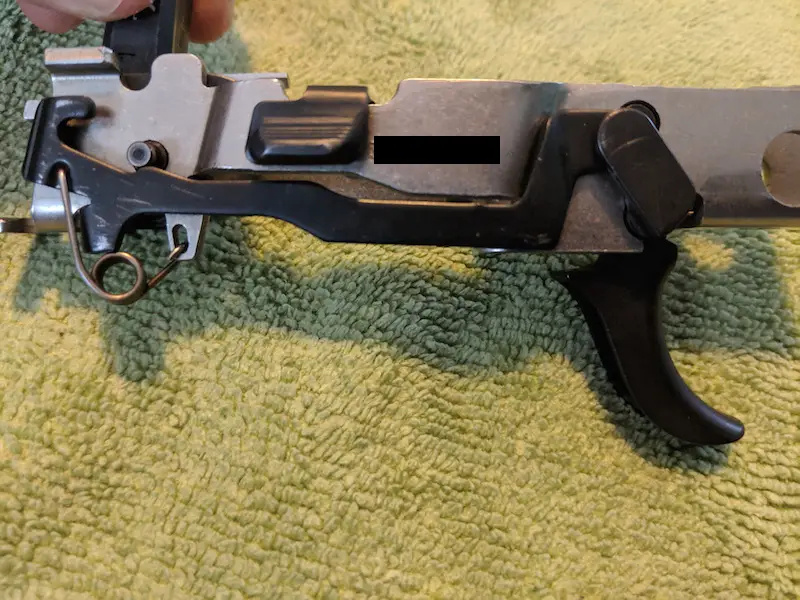
fig. 15 – all pins should be flush on this side, except for the pivot pin which has a more slender knob extended
First, notice that on the bottom of the metal frame of the assembly, there is a small arm that hangs down (See fig. 15) close to the hammer – near my ring finger. On this side, the pins should either be flush (or in the case of the pivot pin is the slender end). Second, you’ll notice a metal piece that extends horizontally close to the top of the hammer (See fig. 16) – overlapping my thumb nail. From this direction, the knobs on each of the pins will be exposed.
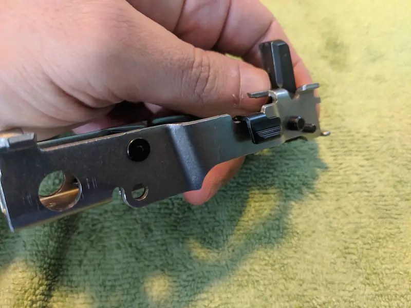
fig. 16 – all knobs exposed on this side
Reassembling the Hammer
The process for putting the hammer back together is slightly different than when it is taken apart. Instead of trying to put the strut pin back in first, you should insert the hammer pivot pin to hold the hammer and safety lever in place. You’ll notice in fig. 14 that there is a large hole in the center of the safety lever. This is where the hammer pivot pin must pass through. This will allow the safety lever to rotate freely.
Once the pivot pin is in place, you can begin the daunting task of compressing the mainsprings to allow you to insert the strut pin. Unfortunately, the only assistance I can provide is to have patience and ensure that you do not allow the springs to be released while under tension. If you do, they’ll go flying. Furthermore, you’ll notice a half-moon type opening in the safety lever in fig. 14. When you put the strut pin into place, you’ll need the strut pin to reside inside this semi-circle. Ensure that the safety lever can still rotate freely after the hammer strut pin and pivot pins are in place.
Slide Catch Lever Reassembly
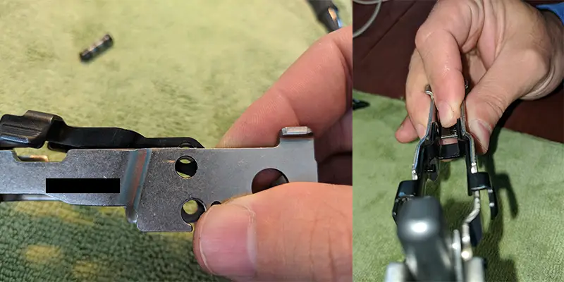
fig. 17 – notice the holes do not line up in the first image, compress using index finger similar to image on right to align and allow pin entry.
The only other piece that you need pay attention to is putting the slide catch lever back into place. I’ve found it best to seat the lever, spring, and washer while the metal frame is upside down. This means you won’t have to worry about the washer falling off. After you have it generally in place, you’ll need to compress the spring in order to allow the pin enter properly (See fig. 17).
Reassembling the P250
If you’ve made it this far, then getting everything else back together should be a breeze. Simply reverse the remaining steps. Put the trigger and trigger bar back in place. Attach the trigger bar spring by place the flat end in the trigger bar, then pressing down to get the hooked end in place on the metal protrusion in fig. 15.
To seat the assembly back in the polymer frame, get the trigger bar spring below the top of the grip module. Next insert the trigger the appropriate hole. You can maneuver the fire control unit forward and use where the grip module narrows to allow clearance to seat the tab at the back of the FCU. Afterwards, insert the takedown lever.
Next, place the barrel and spring into place on the slide. Put the slide onto the grip module and slide it backwards. Use the slide catch lever to hold the slide in the rearward position. Finally, rotate the takedown lever upward, release the slide catch, and you’re back in business. Congratulations!
Parting Shots
Learning how to field strip a Sig Sauer P250 is an acquired skill but with practice things will become second nature. Although things will get easier with time and repetition, it’s important to remember that certain pieces are under tension. Use caution when removing and disassembling the trigger assembly.
If you’ve found this article helpful, please take a look around the site. Let me know in the comments if there’s anything I missed, or is unclear. Also, if you have a particular firearm that you’re having trouble field stripping and need assistance leave your question below. Also, check out the other firearm maintenance articles here.


